A Timer Module is a digital logic circuit that counts up every clock cycle. More functionalities are implemented in hardware to support the timer module so it can count up or down. It can have a Prescaler to divide the input clock frequency by a selectable value. It can also have circuitry for input capture, PWM signal generation, and much more as we’ll see in this tutorial and the next. In this article, we will learn how to configure the timer module of the stm32f103c8t6 to operate in timer mode. We will learn how to calculate the timer preload value(AutoReload value) and also how to select a Prescaler value with any clock frequency of our choice. We will set it up to generate custom delays, which we will use to blink an led. The principles can also be applied to other stm32 variants. So let's get started.
PREREQUISITE
- It is assumed that the reader is familiar with the keil u Vison 5 software environment
- It is assumed that the reader knows how to work the GPIO peripheral
- It is assumed the reader has knowledge about the C programming language
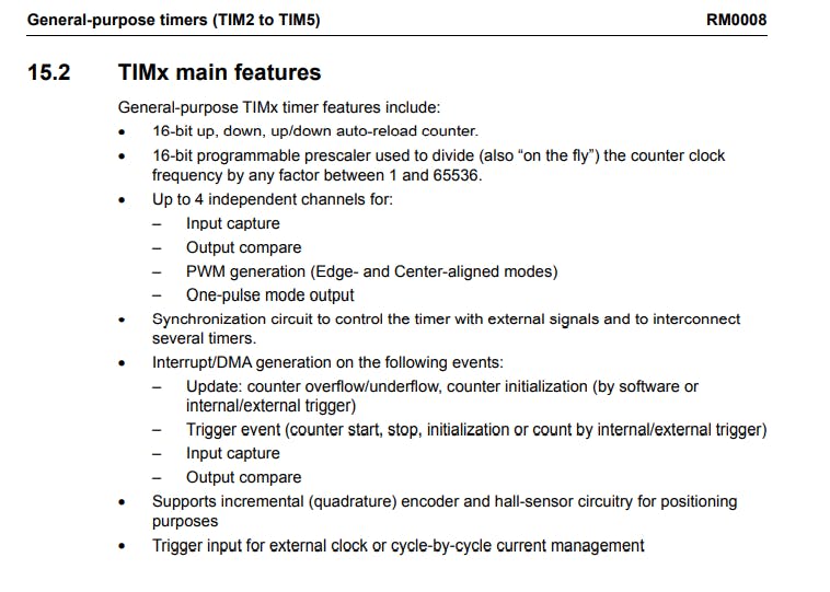
In this tutorial, we are going to make use of General purpose TIMER4. Each timer in stm32f103c8t6 has four-channel, we will be using Channel4 of TIMER4. In a later tutorial, we will use the TIMER4 to generate PWM signals. The features of timer 4 are shown in the picture below.
Figure 1.
From figure 1 above, the timer Module of the stm32 chip is loaded with a lot of features, which we will explore in a later tutorial. For this tutorial let's just focus on the 16-bit auto-reload up, down counter, and also the 16-bit programmable Prescaler. To generate a custom delay we will make use of a particular formula below, please do well to keep this formula in mind or better still write it down, because we will make use of it later on.
Tfreq = Fclock / ( PSC * ARR)
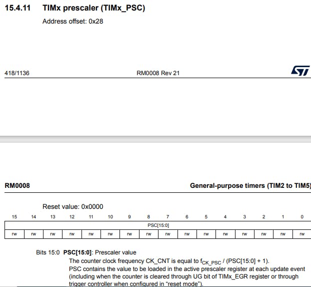
Where Fclock = clock frequency which our microcontroller is running out in this case its 8Mhz Tfreq = the frequency we want for our timer. PSC = the Prescaler value which is between 0 to 65535, what it does is just divide the Fclock. ARR = the Autorelaod register which is also between 0 to 65535. This value is what is actually loaded into the auto-reload register.
Applying little maths on the formula above
PSC * ARR = Fclock / Tfreq. Lets assume our Fclock = 8Mhz.
Tfreq = 1Khz (1ms).
Then :
PSC * ARR = 8000000 / 1000 = 8000.
It, therefore, means, that when the PSC and the ARR value are multiplied it shouldn't be more than 8000. With that in mind we just make PSC = 8 and the ARR = 1000.
Let's get straight to the reference manual of the chip and take a look at Control Register One of the TIMER4.
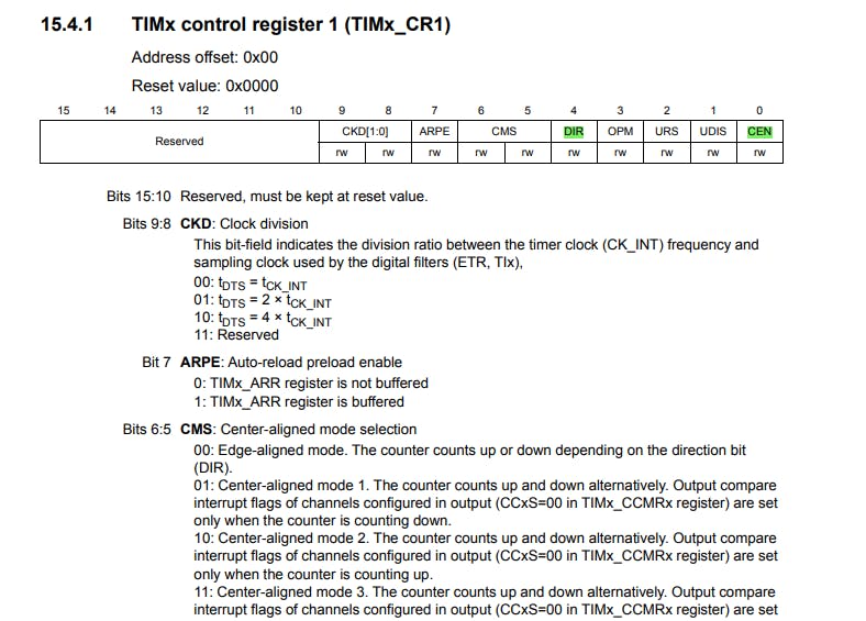
From figure two above, the 4th bit and the 0th bit are highlighted, those are the bits we need in this tutorial. The 4th bit is the direction bit, it determines if the counter would be used to count up i.e from 0 to 65535 or if it will be used to count down from 65545 to 0. After setting up the module, the 0th bit is used to enable the timer or disable it by setting the bit or clearing it respectively. For the tutorial, we are going to use the timer in up counting. In up-counting mode, the counter counts from 0 to the auto-reload value (the content of the TIMx_ARR register) which can be from 0 to 65535, then restarts from 0. In the formula above we are able to calculate a value of 1000 for the auto-reload register, it means that the counter register counts up to 1000 and overflows if the interrupt is enabled it generates an interrupt whenever the value counts up to 1000. The counter register is a 16bit counter shown below it holds the current value of the timer.
A picture of the Prescaler register can be found below :
Things needed for this project inlcude:
- LED
- Jumper Wires
- BreadBoard
- ST Link v2 (External programmer)
- STM32F103 Bluepill or Maple Mini
- Resistor 1KiloOhm
- Keil u Vision5 software
- STM32F103C8xx Reference Manual and Datasheet
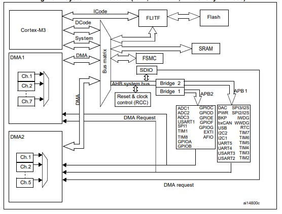
For this tutorial we are going to make use of the CMSIS( common microcontroller software interface standard) library from ARM technology. Let us take a look at the stm32f103c8t6 block diagram below. It is based on a high-performance ARM - M3 32bit RISC.
From figure 5 above. TIMER4 is located at the APB1 bus and GPIOA is located at APB2 bus. So then let us fire up our Keil u vision5 to create a new project.
In the main.c file, add the code snippet below and compile the code below to ensure everything is working properly, we should get a message as shown below.
     #include <stm32f10x.h>


int main(void)
{

while(1)

{


}


}
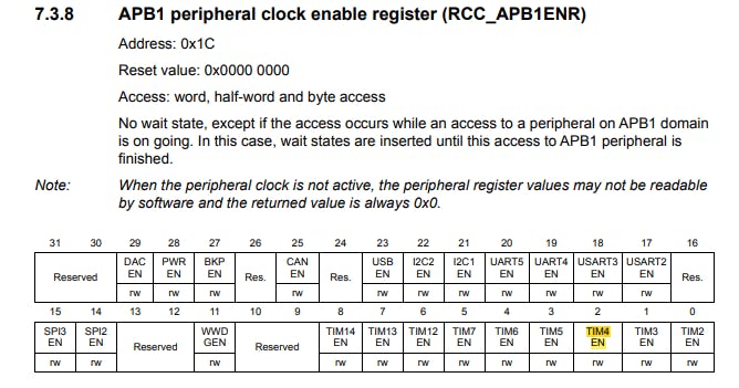
With all that done, we now enable the clock of our TIMER4 and also our GPIOA. We navigate through our Reference manual. This can be done in the Reset and clock control Register(RCC) register of our microcontroller, RCC APB2 peripheral clock enable register(RCC_APB2ENR) to be more precise, here we enable the GPIOA clock by writing a 1 to it, and on the RCC APB1 peripheral clock enable register(RCC_APB1ENR) we enable the TIMER4 clock by writing a 1 to it.
        RCC -> APB2ENR |= ( 1 << 2 );
        RCC -> APB1ENR |= ( 1 << 2 );
Then we next write the values we calculated earlier to the PSC and the ARR register
    TIM4->PSC = 8;
    TIM4->ARR = 1000;
Next, we go to the TIMER4 control register 1 to enable bit 2 of the register which is URS (update request source), by writing a 1 to this bit we are telling the microcontroller that only counter overflow/underflow generates an update interrupt. Next, we go to the TIMER4 DIER register and enable the first bit, by writing a 1 to it, the first bit is the UIE(update interrupt enable), writing a 1 to this bit enables the update interrupt of the TIMER4. Lastly, we go to the TIMER4 EGR register to enable the first bit, by writing a 1 to it. the first bit is the UG(update generation bit), writing a 1 to this bit Re-initialize the counter and generates an update of the registers.
    TIM4->CR1 |=  ( 1 << 2 );
    TIM4->DIER |= ( 1 << 0 );
    TIM4->EGR |=  ( 1 << 0 );
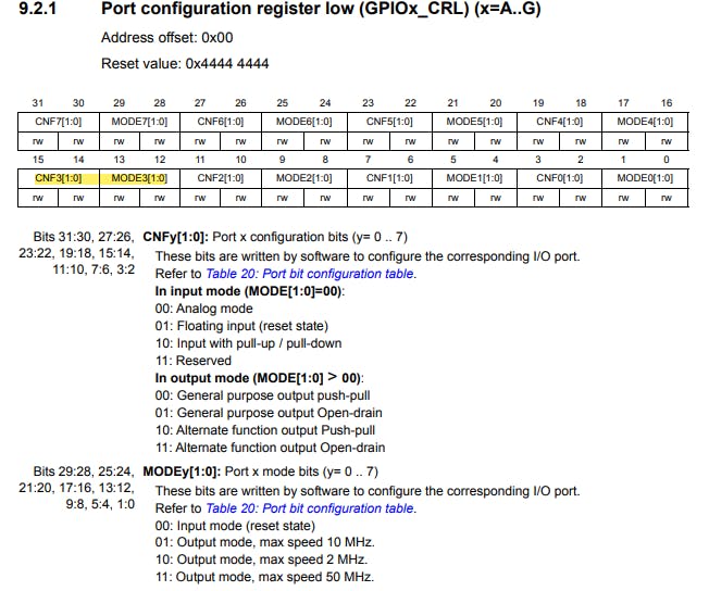
Next we now configure the GPIOA Pin3 as and ouput pin.
    GPIOA->CRL &= ~(0x0F << 12);
    GPIOA->CRL |= (3 << 12);
Next TIMER 4 interrupt request is sent to the NVIC EnableIRQ, later tutorial we will talk more about the interrupts of the STM32F103c8
NVIC_EnableIRQ(TIM4_IRQn);
We then create a function for delay
void delay_ms(int ms) {
    timerTick = 0;
    TIM4->CR1 |= 1 << 0;  //  enable timer 4 start counting upward
    while (ms > timerTick);
    TIM4->CR1 &= ~TIM_CR1_CEN; // disable timer 4 to stop counting
}
Now everytime the TIMER4 counter register counts up to the ARR register and an overflow occurs, the TIMER4 interrupt function handler is called.
void TIM4_IRQHandler(void)
{
    timerTick++;

    TIM4->SR &= ~(1<<0);  // clearing the update interrupt flag in the status register of TIMER4
}
That is all about the code, putting the code together we have:
#include <stm32f10x.h>

#include <stdint.h>

void customTimer_Init(void);

void TIM4_IRQHandler(void);

uint16_t timerTick = 0;

void delay_ms(int ms);

int main(void)
{
    customTimer_Init();

    RCC->APB2ENR |= 1 << 2;
    GPIOA->CRL &= ~(0x0F << 12);
    GPIOA->CRL |= (3 << 12);


  while (1)
  {
        GPIOA->ODR |= 1 << 3;

        delay_ms(1000);

        GPIOA->ODR &= ~(1 << 3);

        delay_ms(1000);
  }

}


void customTimer_Init(void)
{
    RCC->APB1ENR |= 1 << 2;  // timer clock enable
        TIM4->PSC = 8;
        TIM4->ARR = 1000;
        TIM4->CR1 |=  ( 1 << 2 );
        TIM4->DIER |= ( 1 << 0 );
        TIM4->EGR |=  ( 1 << 0 );
        NVIC_EnableIRQ(TIM4_IRQn);
}


void delay_ms(int ms)
{
    timerTick = 0;
    TIM4->CR1 |= 1 << 0;  //  enable timer 4 to start counting upward
    while (ms > timerTick);
    TIM4->CR1 &= ~TIM_CR1_CEN; // disable timer 4 to stop counting
}

void TIM4_IRQHandler(void)
{
    timerTick++;

    TIM4->SR &= ~(1<<0);  // clearing the update interrupt flag in the status register of TIMER4
}
CONCLUSION
This is all for this article, if you encounter any problem please do well to reach out to me via the comment section. Thanks for reading, see you next time.
Linkedln : [linkedin.com/in/osonoderin-wilson-08922b230]
#Embeddedsystems #Tech #Microcontroller
REFERENCES
